Salamina

Overview

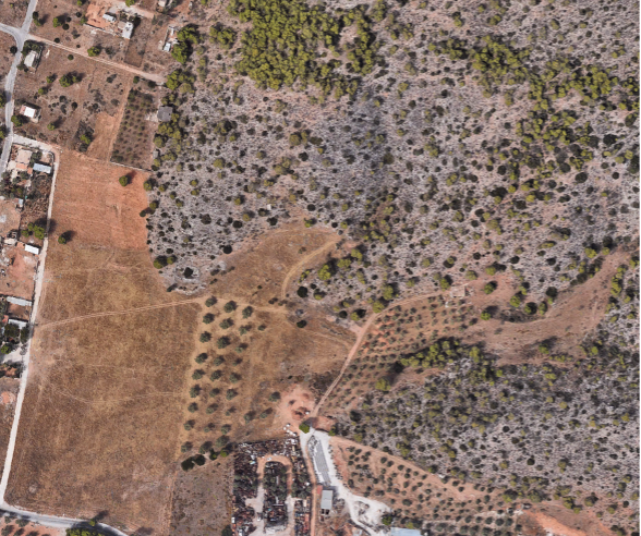
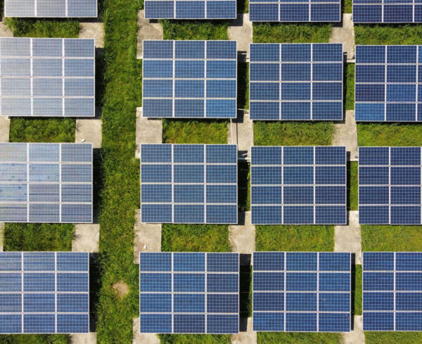
The installation site of the photovoltaic (PV) park is located at the location "Goova Batchi", Municipal Community of Salamina. The area of the plot is 6.740,71 m² and the total surface area covered by the photovoltaic panels is 5.234,798 m².

BASIC EQUIPMENT

PV PLANS

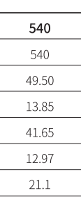
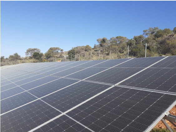
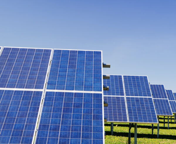
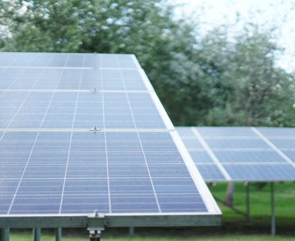
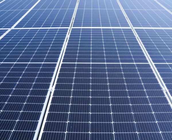
The PV panels will be made by the Chinese company Longi and will be installed in a total of 925 pcs, all of the same nominal power of 540W and must all have exactly the same geometric dimensions. The type of chassis is Longi LR5-72HPH 540M. Upon delivery, or prior this, the PV frames will be accompanied by Flash Reports indicating their "Flashed Power" as measured for each one individually (together with the unique manufacturer's number - barcode) before leaving the manufacture factory.

POWER INVERTERS

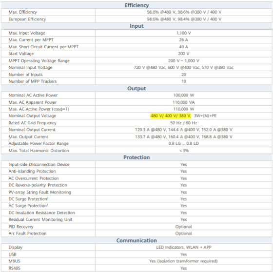
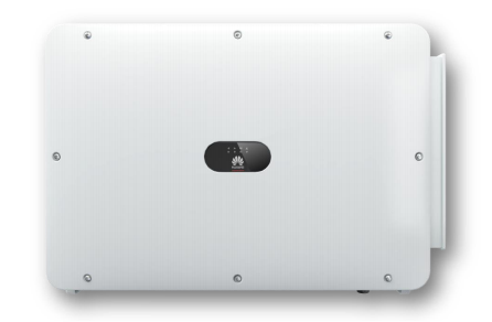
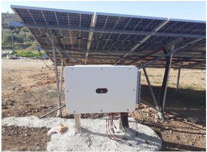
The inverters will be of the Chinese manufacturer Huawei and will be three-phase, "string inverter" type, they will connect parts of the PV system directly to the grid and will have IP65 protection (waterproofing class) for outdoor installation. A total of 5 inverters will be installed. The type of inverters is Huawei 100KTL-M0. They have CE certification and follow the safety standards: IEC/EN 62109-1, IEC/EN 62109-2, EN 61000-6-2, EN 61000-6-3, EN 61000-3-11, EN 61000-3-12 They also follow the following network standards: CEI 0-21, CEI 0-16, DIN V VDE V 0126-1-1, VDE-AR-N 4105, G59/3, EN 50438 (not for all national appendices), RD 1699, RD 413, RD 661, P.O. 12.3, AS 4777, BDEW, NRS-097-2-1, MEA, PEA, IEC 61727, IEC 60068, IEC 61683, VFR-2014, IEC 62116.

SUPPORT SYSTEM FOR PHOTOVOLTAIC PANELS

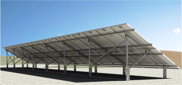
The installation of the PV panels will be carried out on metal fixed supports of the “PROFILODOMI” company made of galvanized-hot-galvanized steel or aluminium profiles, subject to their full compliance with the existing specifications and certifications.

INFRASTRUCTURE PROJECTS

LANDSCAPING OF THE SITE

The PV system site will be properly prepared to facilitate the installation of the PV panel support systems and other equipment based on the site plan, which will ensure the structural adequacy of the installation and the smooth operation of the PV park. Before any other intervention (trenching, etc.), it will be necessary to remove vegetation and level the ground over the entire area of the site (10-20 cm deep) using appropriate earthmoving equipment. In special cases of land where local conditions make it necessary, additional earthworks may be carried out after a study and in consultation with the project supervisor, such as the spreading of broken material, internal roads, drainage works, etc.

FENCING

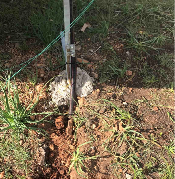
The fence will be made of wire mesh and will have 1 door, sliding or opening, double opening, with a total length of 5 meters. The metal posts (uprights) will be galvanized and will be placed at a distance of 2,5 metres from each other in slots in the ground filled with concrete.

SPECIFICATIONS OF FENCING MATERIALS

Wire mesh 2,00 m high, 55 x 55, wire thickness 2,7 mm (N16) Galvanized pipe stake with a diameter of Φ60 mm B.T. (hot-dipped - seamless), total height 3,00 m with a bend of 0,50 m, Braces of similar pipe 2,50 m high. PVC tap on the pipe holes. Galvanized connectors for the struts Barbed wire Wire N. 16 Wire for tying N.11 Concrete C16/20

SUBSTATION

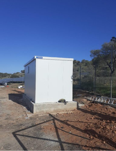
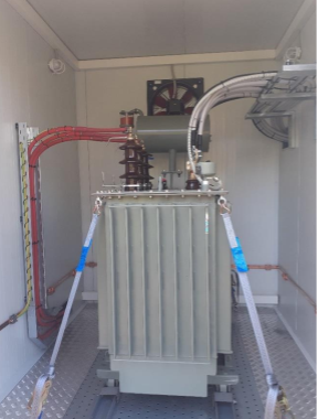
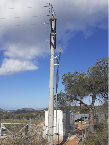
A 500 KVA substation will be installed at the southwestern point of the site to collect the power from the inverters with the least losses. The characteristics of this substation are detailed below.

General characteristics

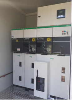
Metal-clad SM6-24 fields of the new SCHNEIDER ADVAN6 series

ELECTRIC (SE) suitable for indoor installation.

They are of module type which enables expansion on both sides of the panel. The fields are in compliance with all international IEC standards concerning the construction of the and materials of medium voltage panels.

The construction of SM6 panels is in accordance with the ISO9001 quality regulation. All necessary certificates are available.

Each SM6 ADVAN6 series cell meets all safety requirements

of personnel and equipment.

SM6 Field Description

The following description contains general information about the SM6 type fields. The Schneider SM6 Advan6 range of Medium Voltage Panels are manufactured in accordance with the international standard for the construction of M.T. panels (for voltages from 1 – 52 kV) IEC 62271-200

Switch compartment:

Contains the disconnector or load disconnector and the breaker ground. The switchgear compartment contains the disconnector or the load disconnector and the earth electrode. The disconnector or the load disconnector is mounted horizontally and the position of the contacts is visible from the front of the field.

Dairy apartment:

Includes three parallel, horizontally fixed bars which are made of electrolytic copper and have PVC insulation. The access to the building is provided by a steel structure with a steel frame and PVC reinforced with PVC. This compartment can be accessed only from the top of the panel, after removal of the roof, which is marked with a warning sign.

Automatic power switch & power cable connection compartment or and fuses:

The compartments are designed to accept for connection of dry type cables and impregnated paper. The connection is made from the bottom and front of the front of the cell. Access is only possible when the earthing is in and after removal of the earthing the door of the hive.

Operating mechanism compartment:

This compartment contains the operating mechanism for operating the switch.

This is the mechanism for the switch’s operating system. The switch may be either a switch or a circuit breaker, or it may be an isolating switch or a circuit breaker.

A mimic diagram shall be provided on the front panel which accurately depicts the three (3) positions of the switch,

Open – Closed – Grounded

Low voltage compartment:

It is at the top of the cell and contains the auxiliary equipment . Depending on the type of equipment, it is located at the top of the cabinet and includes auxiliary equipment.

Depending on the need for auxiliary equipment, three solutions are offered with a height of 1600mm, 1700mm and 2050mm.

Decouplers / Load disconnectors

Depending on the type of field and application, the following switches are available

Disconnectors ‘’Schneider’’ :

CI1 : Load disconnector.

CI2 : Load disconnector.

CIT : Load disconnector.

CS1 : Load disconnector.

All switches are mounted in a common shell. They have as insulating gas SF6 at low pressure and without the need for maintenance or refilling, throughout the entire throughout their life cycle, which is thirty (30) years of normal operation.

F6 Automatic Power Switches

SF1 type automatic power switches are used. They have SF6 gas as an insulator in low pressure and without the need for maintenance or refilling, throughout the entire duration of the life cycle of thirty (30) years of normal operation.

Available from auxiliary position indicator contacts and, depending on the application, can be equipped with a motor remote control, control coils (opening, closing and voltage drop) and low power consumption that does not require an auxiliary operating voltage.

It may be of the fixed type or of the detachable type.

Automatic vacuum circuit breakers

EVOLIS type automatic power switches are used. They have vacuum as an insulator.

It has auxiliary position indicating contacts and, depending on the application, can be equipped with remote control motors, control coils (opening, closing and lack of voltage).

It may be of the fixed type or of the detachable type.

Voltage transformers

The voltage transformers are conventional, made by Schneider and in accordance with the standards.

They are available both with and without fuses.

Either three (3) single pole or two (2) double pole can be used.

Voltage transformers

The voltage transformers are conventional, made by Schneider. They can have two secondary for measurement and protection. Alternatively, current sensors can be used low power current transformers.

Low voltage cables

Low voltage cables are characterized by the self-extinguishing property in case of fire and insulated up to a voltage level of 1000 V and covered with PVC material.

Diameter of the cables used is:

Current circuits : 2,5 mm²

Automation and voltage circuits : 2.5 mm².

Each cable is marked both at the beginning and at the end of the cable.

Metal Construction / Corrosion Protection

For the proper operation of the equipment in any climatic conditions, the following measures have been taken during the manufacturing process:

The visible external field surfaces at the front of the cells are

the front of the cells are made of galvanised sheet metal (coating thickness : 3 m).

The surfaces are then subjected to cleaning with a phosphoric salt solution before proceed to the painting stage. The paint is made of polymerized polyester epoxy

The paint colour is RAL 9003 (white).

As regards the other surfaces, hot galvanised sheet metal with a medium of

the average thickness of the coating is 20 m and which has been chrome-plated.

Cable connection

The indicated terminal boxes for the connection of cables may be cold-cooled and heat-cooled types (heat-cooled types are preferred) for cables with dry insulation or cables insulated with impregnated cable insulation paper. The maximum permissible cross-section of cables for standard equipment is:

Unipolar

■ 630 mm² or 2×400 mm² for 1250A cells

■ 50 – 240 mm² for 630A or 400A cells

■ 95 mm² transformer protection cells with fuses


Three poles

■ 50 – 630 mm² for 1250A cells

■ 50 -240 mm² for 630A or 400A cells


Checks – Tests

The standard checks of the equipment take place in our factory and are in accordance with IEC standards:

■ Mechanical function and interlock check

■ Compatibility with technical drawings

■ Check of interchangeability of moving parts

■ Dielectric test of the main circuit at an industrial frequency of 50kV 50Hz/1min

■ Functional test of the HT circuit

Standards & Quality Certificates

Standards

The equipment offered has been designed, manufactured and tested in accordance with international standards listed below:

IEC standards

62271-200 High-voltage switchgear and control gear – Part 200: A.C. metal
enclosed switchgear and control gear for rated voltage above 1 kV
and up to and including 52 kV.
60470 Medium Voltage Relays.
62271-103 High voltage switches – Part 1: switches for rated voltages above 1 kV
and less or equal to 52 kV.
62271-105 High-voltage switchgear and control gear – Part 105: High voltage
Alternating current switch-fuse combinations.
60801 Electromagnetic Compatibility for measurement instruments
62271-100 High-voltage switchgear and control gear – Part 100: High-voltage
alternating current circuit breakers.
62271-102 High-voltage switchgear and control gear – Part 102: High-voltage
Alternating current disconnectors and earthing switches.
60044-1 Instrument transformers – Part 1: Current transformers.
60044-2 Instrument transformers – Part 2: Voltage transformers
60044-8 Instrument transformers – Part 8: Low Power Current transducers
60529 Ingress Protection rating.
60694
60255
General Specifications for Medium Voltage Panels
Protection Relays

Certificates of Quality

The quality system for the design and manufacture of SM6 series cells is harmonized with the requirements and standards of ISO 9001 quality regulations.

CABLE ROUTING – WELLS

Tubes

The cables will be routed within double-wall high-density polyethylene (HDPE) cable protection pipes used in underground electrical and telecommunication installations. High-current cables shall be routed in a separate tube from low-current cables.

The tube shall consist of two co-extruded walls, structured externally for greater impact resistance, lower weight and greater flexibility and smooth internally to facilitate the passage of cables. The two walls cannot be separated due to the production process (co-extrusion). The pipe must have a connection fitting (muff).

The cables are routed from the manholes to the HPT in spiral pipes. All spiral pipe ends and cable connections will be made in protective tapes and collars to maintain consistency and avoid damage from external factors.

TECHNICAL CHARACTERISTICS

Construction: The Double Wall Structured Pipe is made of high density polyethylene with UV protection for underground electrical and telephone cables. It is made of two structured walls: the outer wall is spiral to provide flexibility and to ensure greater resistance to deformation. The inner wall is smooth to facilitate the insertion of cables. Produced according to CEI EN 50086-1 (CEI 23-39), CEI EN 50086-2-4 (CEI 23-46).

Application: Highly demanding protection for electrical and telephone installations. Suitable for all types of underground electrical lighting & signalling networks with excellent strength and high flexibility. Additional external protection for water or gas pipes.

Temperature resistance: -25o C/ +60o C

Minimum radius of curvature: 8 times the outer diameter.

Deformation resistance: > 450 N with a deformation of the inner diameter equal to 5% (in accordance with EN 50086-2-4 CEI. 23-46).

Maximum elastic strength of cable guide: > 650 N

Components: Each reel contains both a guide (steel fibre) for easy pulling of the cable, a connection fitting (muff), and optionally an elastic ring for airtight sealing

Dielectric strength: > 800 kv/cm.

Electrical insulation resistance: >100 M Ω.

Composition: polyethylene: 97%, dyes: 2%, additives (UV protection): 1%.

PIPE INSTALLATION

A trench 60 cm deep is created for the installation of the pipes.

The bottom of the trench and the fill up to 10 cm above the pipe generally consists of sand to create a continuous and flat surface. The pipe shall be supported on a thin layer of sand 10 cm high. The remainder of the trench shall be filled with the excavation products.

BREASTS

All manholes will be made of polypropylene, very resistant to impact and temperature. The manholes will have stoppers for joining with pipes and the upper part will have a frame for the installation of an airtight cover. Their dimensions shall be suitable for the visit of the cables. Manholes shall be installed every 25 metres of the length of the ducts where there is a change of cable direction and in the case of branches.

Electrical equipment

For the electrical connection of the PV panels, a special type of cable will be used, with integrated positive and negative pole contacts. The conductive material of the cable is copper of suitable cross-section. The cable is flexible, non-combustible and has specifications for protection against ultraviolet radiation and operation at high temperatures. In particular, the extreme operating conditions for the PV panel connection cable are from -400C to +1000C. The polarity of the cables shall be identifiable as well as their connection points to the electrical devices of the PV system.

The DC cables shall be routed on the metal scaffolding.

CABLES A.C.

For the AC section of the PV Park and specifically for the connection of the DC/AC inverters to the main panel of the PV Plant, cables of type NYY (J1VV-R) manufactured according to VDE-0271 will be used.

The cross-sections of the cables and conductors shall be such that the voltage drop, under NOCT conditions and at MPP voltage, from the output of the PV Panels up to the inverters is less than 1%.

COMMUNICATION CABLES

The signal cables, which will also be installed in plastic underground pipes, are:

UTP cable for image transmission from the cameras

LIYCY(TP) for the transmission of signals from the inverters and other sensors to the control centre.

EARTHING AND LIGHTNING PROTECTION

Grounding, external protection and equipotential protections of the park.

The earthing (external protection and equipotential connections) shall comply with IEC (EN) 62305 – 3 for Protection Level III.

GROUNDING CONSTRUCTION

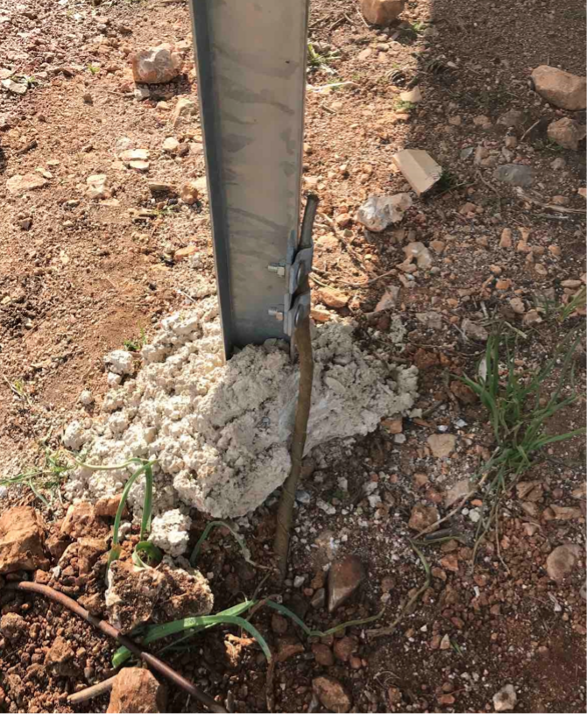
For the construction of the grounding, a 30×3,5mm tape should be placed at a depth of at least 0,5 m from the ground and in a grid arrangement under the space to be occupied by the supports. The tape shall be of St/tZn 30×3,5mm. It will be supported by stakes every 2 metres on the ground. The connections between the strips will be implemented with tape/tape connectors. The conductors that will end at the pins (pin earthing) and the conductors that will be used in the equipotential protection of the metal bases of the photovoltaic cells will be connected to the tape with steel connectors. The conductors will be Φ8 made of St/tZn. The connections of the bases to the conductor will be implemented using connectors of type (H) 6-10mm St/tZn. At the points where the conductors (equipotential and pin grounding) leave the ground they must be covered (30cm on the ground and 30cm in the air) by the special anti-corrosion tape. In addition, the equipotential protection conductor shall not be directly connected outside the ground to a pin earth conductor. Finally, an equipotential yoke has also been calculated for earthings in the inner space of the house or the outer pillar of the installation.

Selection of clamps

Connections between the earthing materials and the remaining conductors shall be made with connectors fitted with bolts and screws of certified 100kA 10/350msec dissipation capacity.

Protection of electrical and electronic devices from shock surges.

Protection of the general panel of the H.T. installation from direct and indirect lightning strikes in the alternating current:

For the general panel of the installation it is required to place a device parallel to the three phases and the neutral versus ground. The device directly and indirectly absorbs lightning strikes from the AC network up to 100kA of 10/350 sec waveform leaving a residual voltage <=1.5kV. The device bears the quality marks of independent laboratories KEMA, VDE, UL, VdS on testing of the device according to the standards and technical characteristics indicated by the manufacturer.

Protection of general self-consumption panel from direct and indirect lightning strikes in AC

To protect the park’s general self-consumption panel, it is necessary to place a device parallel to the three phases and the neutral against grounding. The device directly and indirectly absorbs lightning strikes from the AC network up to 50kA waveform 10/350msec leaving a residual voltage <=1,5kV

Protection of self-consumption sub-panels from indirect lightning strikes in AC

To protect the 3F sub-panels requires the placement of a device parallel to the phases and the neutral against grounding. The device indirectly absorbs lightning strikes from the AC network up to 40kA of 8/20msec waveform leaving a residual voltage <=1.25kV. The device bears the quality marks of independent laboratories KEMA, VDE, UL, VdS on testing of the device according to the standards and technical characteristics indicated by the manufacturer.

Protection of the communication circuits of inverters (RS 485)from indirect lightning strikes in DC

For the protection of the RS 485 communication device of the inverters a surge arrester will be installed. The device protects a two-wire line and indirectly absorbs lightning strikes up to 10kA of 8/20msec waveform leaving a residual voltage <=27V. This device has a cut-off frequency of 250 MHz (suitable also for High Frequency) and bears the quality marks of independent GOST laboratories on testing of the device according to the standards and technical characteristics indicated by the manufacturer.

Protection of a simple two-wire telephone line from direct and indirect lightning strikes in DC.

A surge arrester will be installed to protect a single telephone line. The device protects a two-wire line and absorbs direct and indirect lightning strikes up to 5 kA of 10/350 msec waveform leaving a residual voltage <=270V. The device bears the quality marks of independent laboratories CSA, GOST on testing of the device according to the standards and technical characteristics indicated by the manufacturer.

CCTV circuit protection indirectly lightning strikes on DC

A surge arrester will be installed to protect a simple telephone line. The device protects the coaxial conductor of CCTV circuits indirectly lightning strikes up to 10 kA waveform 8/20 msec leaving a residual voltage <=25V. The device bears the quality marks of independent GOST laboratories on testing of the device according to the standards and technical characteristics indicated by the manufacturer.

MONITORING SYSTEM OF A PV STATION

The installations will include appropriately selected sensors for measuring meteorological parameters and data of the PV park’s operation, i.e. solar radiation intensity sensors, external temperature and operating temperature sensors of the PV generators, instantaneous power and energy meters at the output of the PV and the inverter, etc. The continuous recording system of the system operating parameters shall be compatible with the inverter technology. The monitoring system will be able to record and store the data to allow continuous analysis of the PV farm performance.

They are installed directly on the PV panels and measure the incidence of solar radiation and the temperature of the panel. They perform a continuous comparison of normal/theoretical values of the installation power. This ensures easy detection of shadows, impurities or a prolonged power reduction in the PV panel. Additional sensor connections for optimum measurement of ambient temperature or wind speed allow even more precise calculations.

The monitoring system provides the possibility of monitoring the performance and output of the system as well as all the measurement parameters of the sensors at any time and from anywhere via the internet, provided this possibility is available.

SECURITY SYSTEM

Perimeter Fence Breach Detection System:

For the security of the station, an alarm system will be installed which will consist of 4 laser beam detectors with laser beams that will prevent any intruder from entering the station. In the event of a breach or damage, the owner and persons or companies indicated by the owner will be notified by message.


CTV Closed Circuit Television Surveillance System:

Consists of 4 fixed outdoor cameras arranged around the perimeter of the installation. The cameras will be mounted on hot-dip galvanized masts. The cameras will monitor the site and record throughout the day and night. The data will be stored locally on hard drives. As soon as a breach of the premises is detected, the data will not only be recorded locally but will also be sent via the network to the system management company and the owner.

Lighting:

HQI reduced-power floodlights will be installed on the camera projectors. In the event of an alarm, a command will be given to switch on the floodlights.

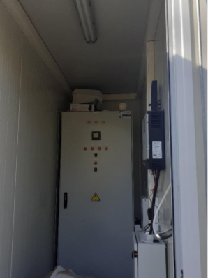
The alarm panel will be located within the control house, as will the other alarm, lighting and CCTV system devices. A 1KVA UPS shall be installed within the control house to power the park’s security and monitoring systems in the event of a mains supply failure.

The number of beams and cameras can be changed according to the shape of the perimeter of the field.

CONNECTION TO THE NETWORK

The connection of this project to the network will be made by underground cables of appropriate cross-section to minimise losses.

The point of connection of the project to the network will be determined by the DEDDHE.

More Case Studies